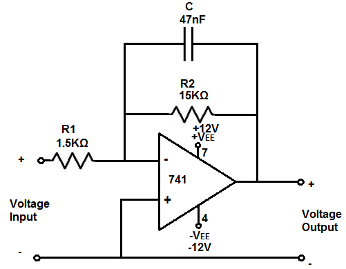

Pass filter because of the reactive properties of a capacitor.
Low pass opamp filter designer series#
When a resistor is placed in series with the power sourceĪnd a capacitor is placed in parallel to that same power source, as shown in the diagram circuit above, this type of circuit forms a low pass filter. The resultant value of theĬutoff frequency calculated is in unit hertz (Hz) for frequency, farads and microfarads for the capacitor, and ohms(Ω) for the resistor.Īn RC low pass filter is a filter circuit, composed of a resistor and a capacitor, which passes low-frequency signals andīlocks high frequency signals. After 2 values are entered in, the user clicks the 'Calculate' button, and the result isĪutomatically computed. This calculator allows a user to select the magnitude of the units of the capacitor, including picofarads (pF), nanofarads (nF), microfarads (♟), and farads (F),Īs well as the unit for resistance and frequency.

To use this calculator, all a user must do is enter any values into any of the 2 fields, and the calculator will calculate the third field. Of the circuit, according to the formula f c= 1/(2πRC). This passive RC low pass filter calculator calculates the cutoff frequency point of the low pass filter,īased on the values of the resistor, R, and the capacitor, C, Constrain the filter order to 120.Enter in Any 2 Fields To Compute the Value of the 3rd Field The passband ripple is 0.01 dB and the stopband attenuation is 80 dB. The stopband-edge frequency is determined as a result of the design.ĭesign a lowpass FIR filter for data sampled at 48 kHz. This function designs optimal equiripple lowpass/highpass FIR filters with specified passband/stopband ripple values and with a specified passband-edge frequency. In the DSP System Toolbox, the preferred function for lowpass FIR filter design with a specified order is firceqrip. FIR design functions in the Signal Processing Toolbox (including fir1, firpm, and firls) are all capable of designing lowpass filters with a specified order. Another common scenario is when you have computed the available computational budget (MIPS) for your implementation and this affords you a limited filter order. One such case is if you are targeting hardware which has constrained the filter order to a specific number. There are many practical situations in which you must specify the filter order. FIR Lowpass Designs - Specifying the Filter Order However, the use of minimum-phase and multirate designs can result in FIR filters comparable to IIR filters in terms of group delay and computational efficiency. IIR filters also tend to have a shorter transient response and a smaller group delay. IIR filters are generally computationally more efficient in the sense that they can meet the design specifications with fewer coefficients than FIR filters. IIR filters (in particular biquad filters) are used in applications (such as audio signal processing) where phase linearity is not a concern. FIR filters are also used in many high-speed implementations such as FPGAs or ASICs because they are suitable for pipelining. FIR filters also tend to be preferred for fixed-point implementations because they are typically more robust to quantization effects. You generally choose FIR filters when a linear phase response is important. When designing a lowpass filter, the first choice you make is whether to design an FIR or IIR filter.


 0 kommentar(er)
